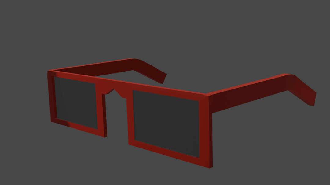
I started playing around with Blender to learn 3D modeling and animation in 2020. I loved the experience but I had trouble understanding some concepts and terms. I would have found a concept guide useful at that time so this is my attempt at providing that!
3D models are defined by two important things: shape and color. The shape defines the surface of the object in 3D space. The color describes how it looks. 2D art, like painting, is similarly interested in shape and color but 3D models are a lot more computer-oriented. How the shape and color are managed in 3D graphics is tightly coupled with how computers best understand it.
Shape
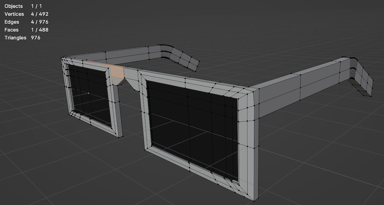
The first part of a model that you worry about is the shape.
When you draw in 2D, you draw your subject from some perspective. You have to do the heavy lifting of thinking about how the subject will look from your chosen perspective and your drawing will only contain information from that perspective. When you do 3D modeling, you try to describe the shape of the object from all perspectives because you try to capture the shape of the object in 3D fully. So you don’t have to solve the perspective problem but you have to instead think about the full shape of the subject. That’s the trade-off between 2D and 3D.
So how is the 3D form of the subject described? Well, when humans wanted to “capture” a 3D shape, they would create a mold of the object. But the mold has “infinite” resolution which computers are not very good at. So instead of wrapping a full mold around the object, imagine putting a tight net or a mesh around the object. Depending on the resolution you want, you can make the mesh finer and finer.
The mesh that is wrapping around our object is made up of squares that are called faces. Each side of the face is called an edge and each corner is called a vertex. The positions of each vertex, edge, and face together represent the shape of the 3D object.
But once we have the ideas of vertices, edges, and faces, we don’t really need our original idea of wrapping a fixed mesh around our object. We can instead just place vertices wherever we want on the object and connect them with edges and form faces. This allows us to have some areas with very small faces to cover more detail and some areas with very big faces to reduce our data usage.
Matter of fact, reducing data usage while capturing important details becomes the core problem in 3D modeling. Since rendering time is directly related to vertex and face count, you want to capture enough details in the mesh to achieve your fidelity goals, while still meeting your rendering time budget. Games, in particular, need to render a frame many times a second and so have to be very careful about their vertex count.
Color
Once you have the shape described, then you have to worry about how the shape should “look”. When you do 2D art, you think about the base colors of the object. But you also have to manually think about how light will interact with the shape of your subject (like what parts of the subject will be in its own shadow or what parts will be highlighted and glossy). Then you have to combine the base color and light effects to render your drawing.
In 3D art, we have already done the tough work of describing the shape of the object in 3D. Wouldn’t it be nice if we just placed some light sources and let the computer figure out how the light would hit this 3D surface and generate the look of the object? Well, fortunately, we can do exactly that! But before we get to how we can do this, let’s dive a little deeper into how we can control how a 3D model looks.
When you render a 3D scene, you place objects, lights, and a camera. Then you tell the computer to render the scene. For each pixel, the computer determines what object is visible in that pixel and picks the vertices responsible for that area of the object1. For the object, it invokes something called a shader to calculate the color value of the pixel. The shader is custom code that can use contextual information (like camera, light, and object properties) and additional data (like image textures) to calculate its output.
Shaders can be very simple (like a shader that always returns a fixed color) or marvelously complex (like generating an alien world or simulating water). A lot of the GPU-based computation used for AI takes its inspiration from capabilities that were created specifically for shaders.
PBR
While writing a custom shader allows you to generate a lot of cool effects, very often you are not looking for cool effects. Instead, you are looking for a “take a base color and add lighting effects” shader. To address this common use case, 3D programs will come with some pre-created shaders.
The most common are shaders that are inspired by real-life physics and thus are called Physically-based renderers (PBR). Depending on the use case of the application this shader will have varying levels of realism and varying numbers of parameters
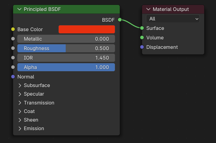

A cool feature here is that you don’t need to choose a single value for the base color and roughness. You can instead choose the input to be an image, called a texture. This allows the color and roughness to vary across the 3D object instead of having one fixed value for all the vertices in the object. So for example, some parts of the object can be white and some parts can be black or some parts can be glossy and some parts can be matte.
UV Mapping and Textures
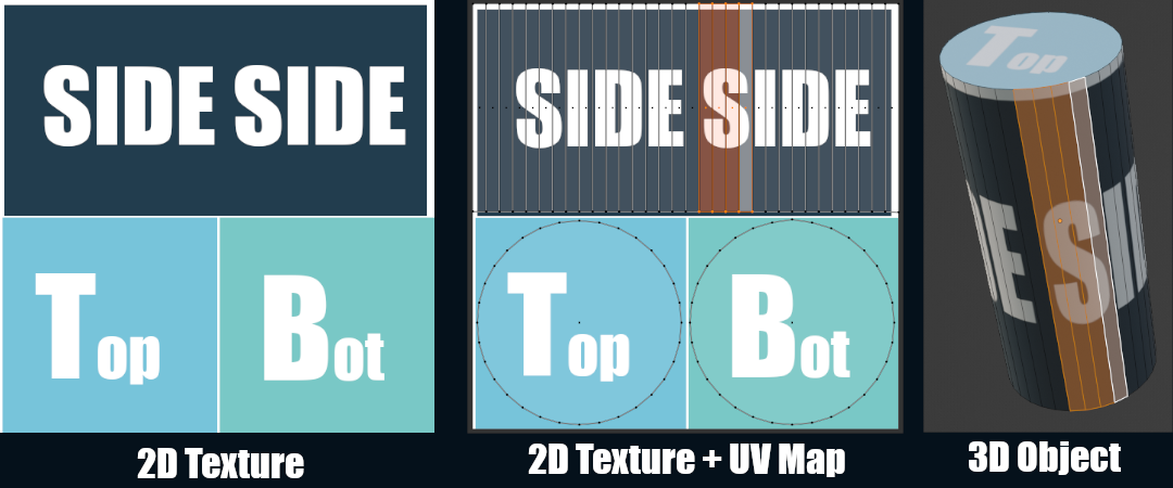
But a problem this raises is: how does the shader decide what part of the image it should be looking at when working on a vertex? This is solved by a process called UV Mapping.
What we really want to do is take our texture and wrap it around our 3D object. In the image above, our texture has different sections we want to use for the side, top, and bottom of the cylinder. To achieve this, we take each face of our 3D object and place it in the appropriate area in our texture. This process creates the mapping–it’s a mapping from the 3D object to the 2D texture. So when the shader is running for a given vertex, it can use this mapping to find what part of the texture it should use in its calculations.
In our example, we said we could place the faces manually to generate our UV mapping. However, some 3D objects can have millions of faces so manually placing each face can be unrealistic. This is why 3D applications will usually have a suite of tools to assist or to automate the UV mapping process.
But what’s up with the name? Mapping makes sense, but where is UV coming from? Well, if we say that the 3D object exists in the x/y/z dimensions, then what dimensions should we use for the texture? To avoid confusion we can use u/v dimension (instead of x/y). Then the UV-mapping maps from the x/y/z dimensions to the u/v dimensions (hence the name).
Materials
So we have a PBR shader and we have the textures we want to use ready. Before you can actually use the shader, you have to create a specific instance of the shader which is called a material. The material allows you to assign the different parameters the shader allows. In some ways, the shader is like a read-only copy and the material is the real instance of the shader that you can tweak and apply to objects.
Materials can also be reused. So for example, if you have a collection of rubber bands where some are red and some are blue. Two materials can be created (based on the PBR shader). One material gets assigned the red color and one material gets the blue color. Then all the red rubber bands can share the same red material and all the blue rubber bands can share the blue material.
So, to summarize, shaders take contextual information and calculate color values. Materials are specific instances of shaders. Textures are images that can be assigned to materials and used by shaders in their calculations.
Adding Details
As I mentioned earlier, balancing the level of detail and rendering cost is a central battle of 3D art. One common rule of thumb is that details in the geometry (vertices/edges/faces) are more expensive than details in the textures since the texture details are a simple lookup in the shader. That’s why a lot of details like wood grain or dirt/grime will be done using textures instead of geometry.
Base color and roughness/smoothness texture maps are great at faking this detail. But they do have a limit. Since the base color and roughness maps don’t generate any real geometry, everything will still look “flat”. They can’t fake details like big bumps or big gaps which will interact with the light differently than the flat geometry.
So what we want is to tell the shader that this area of the object should interact with light as if it were a bump or a gap. How can we do that? Well, we already have the texture set up so if we can encode that information in an image then the shader can do another lookup in that image (using the UV mapping) and adjust its light calculations accordingly.
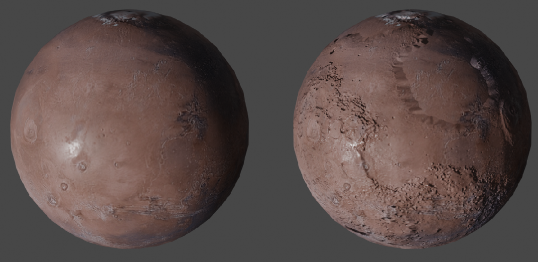
That’s exactly what normal maps do! Normal maps encode which direction that part of the surface is bumping towards. This is done by drawing a perpendicular arrow from the surface and encoding the x/y/z values of the arrow in the r/g/b channels of the image! This way the normal map can represent bumps/gaps in any direction in the 3D space.
While base color textures are sometimes created manually by artists, normal maps are never generated manually. Artists will instead create a highly-detailed version of the 3D object and use the 3D program to calculate the normal map that can be used with a much simpler 3D object.
Trade-Offs
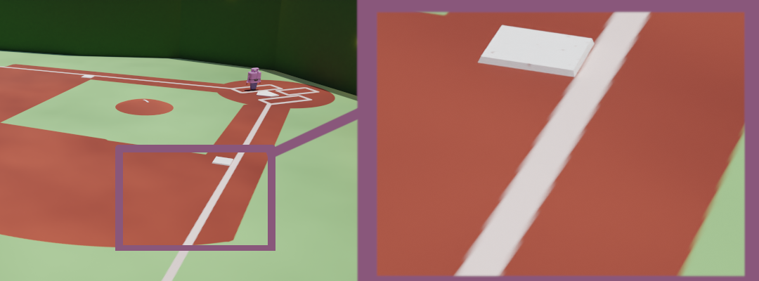
Texture mapping solutions are incredible in how much detail they let you add cheaply. However, they start to fail as the camera gets closer to the object. Since the textures have a fixed resolution, if the camera gets too close to the object then pixelization will start to be visible in the rendered output because the texture itself won’t have enough pixels to show more detail. This can be solved by creating bigger and bigger textures but textures sizes blow up quickly as they are scaled up. For example, a lot of games nowadays will require a 100GB+ download, the majority of which will be high-quality textures.
Due to the impact of texture sizes, it is important to decide when some details should be represented in the geometry, instead of relying on higher-quality textures.
Conclusion
The terms in bold are by far the most important terms to learn:
- Vertex/Edge/Face (together called Geometry)
- Shader
- Texture
- UV Mapping
- Material
- Normal map
While I learned them for Blender, I quickly found that the terms are used by the 3D art community and graphics programming community. It is used by basically all 3D software and game engines.
So, as long as you can remember how the shape of the form is described and how the colors work, you can onboard to any 3D application or system.
Links
If you are interested in learning 3D modeling, I recommend the notoriously popular Donut tutorial. In addition to modeling, it will also help you understand how to use materials and Blender’s node system for creating shaders without coding.
If you are interested in playing around with coding custom shaders, Shadertoy makes it easy and fun to play around with shaders in the browser! In particular, this tutorial is a good introduction to shaders.
If you are interested in how textures are created, here is a texture painting tutorial for Blender. Though admittedly, Substance Painter is by far a more popular tool for this workflow but it’s not free (and it’s Adobe).
For 3D game development, game engines usually have subpar support for 3D modeling. So most often, the 3D models will be made outside of the game engine editor (like in Blender). Then textures will be generated from the 3D application (like Blender or Substance Painter). Then the model and textures will be imported into the game engine. But materials and shaders will have to be created within the game engine since they are so closely tied to the rendering framework that the game engine uses.
Here is an expansive tutorial in Unreal to make a world map with Unreal-specific explanations of shaders and materials. And here is Unity’s node-based system to easily create custom shaders called Shader Graph. Weirdly, as someone making a game in Unity, I have consumed fewer tutorials for Unity–maybe because their docs are good enough!
I am skipping over A LOT of complexity here. How the computer goes from the scene metadata to figuring out what is visible involves a lot of algorithmic cleverness and complexity. However, none of this complexity is necessary to begin working with 3D applications. If you are curious, Ray Tracing in One Weekend introduces one way to go from scene metadata to a final rendering. ↩︎